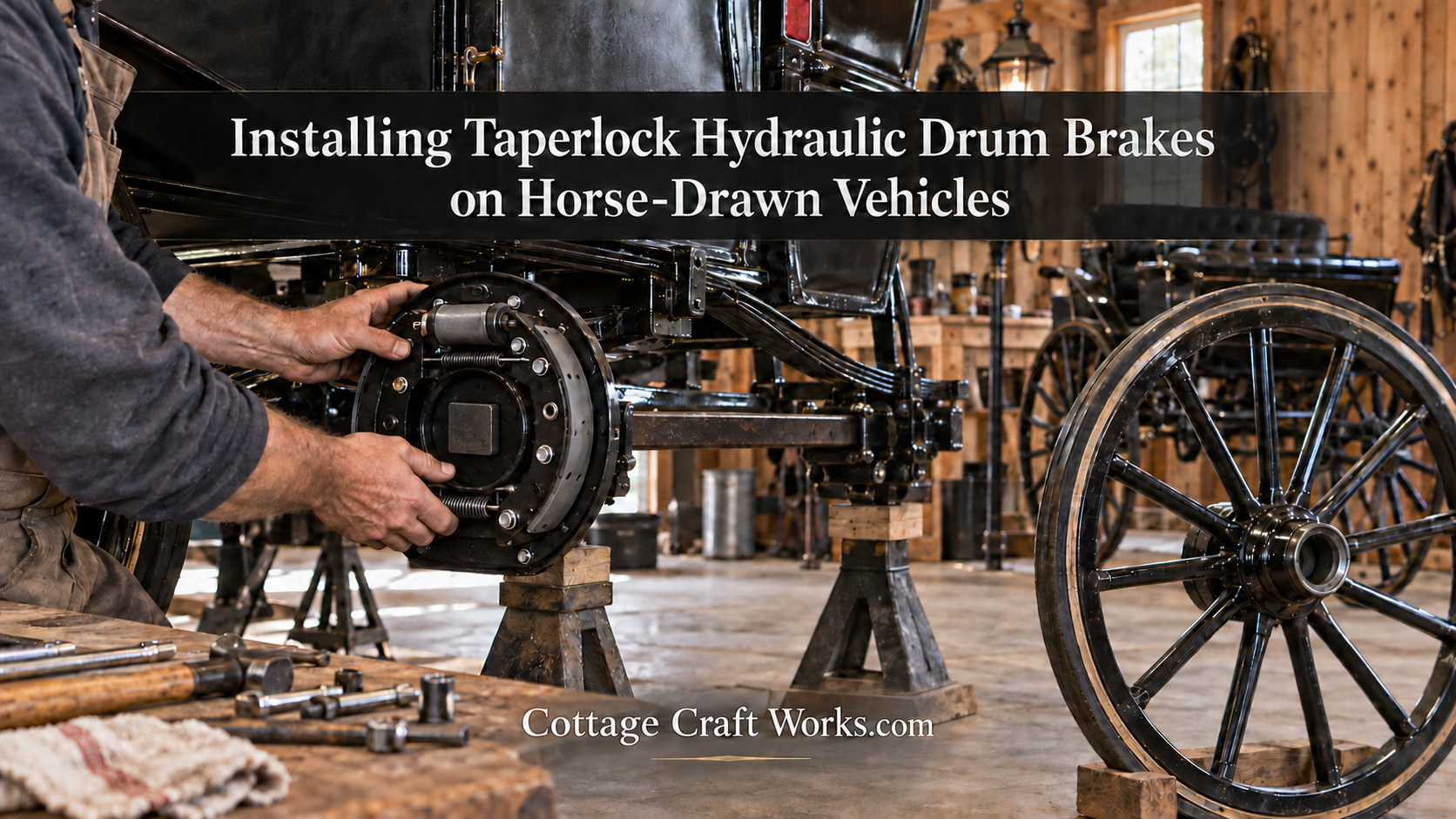

Article
7-inch & 8-inch Taperlock Brake Parts, Wheel Cylinder & Maintenance Guide
What parts should be inspected when maintaining Taperlock horse-drawn vehicle brakes?
Inspect the wheel cylinder and seals, bleeder, shoes and linings, springs, adjuster components, Taperlock wedges and clamp plate, brake lines and fittings, drums, wheel bearings, pedal linkage, and master cylinder.
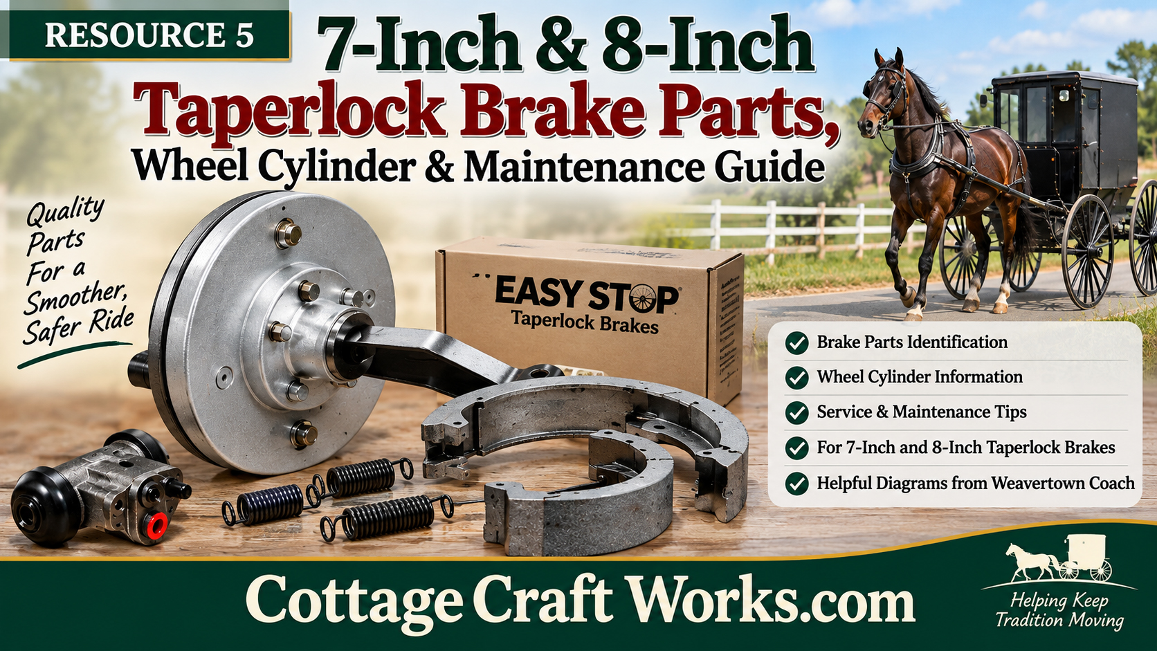
Resource 5
Use the parts diagrams to identify service components before disassembly or ordering replacement parts.
Wheel Cylinder Assembly
The Weavertown diagram identifies the wheel-cylinder assembly as: 3038 bleeder screw; 3115-07 wheel-cylinder housing; 3117-OR O-ring piston; 3117-10 O-ring; 3115-10 brass tubing seat insert; and 3120 dirt cap.
7-inch PA Taperlock Adjuster Brake
Major components include the 3115-USAL wheel cylinder, 3100-15 top spring, axle-size-specific Taperlock wedges and clamp plates, 3051-04 7-inch brake shoes, adjuster cam nut, adjuster cam pin, 1/4-28 x 1-inch Taperlock clamp screws, 3099 bottom spring, wheel-cylinder bolts, adjuster cam washer, backer plate, and adjuster cam.
8-inch PA Taperlock Adjuster Brake
Major components include the 3115-USAL wheel cylinder, hold-down cups, 3050 brake shoes, adjuster cam nut, axle-size-specific Taperlock wedges and clamp plates, shoe hold-down pins, 3103-05 top spring, 3102 bottom spring, backer plate, hold-down springs, wheel-cylinder bolts, Taperlock clamp screws, internal-tooth lock washer, adjuster cam bolt, and adjuster block.
Routine Maintenance Inspection
Use the parts diagrams together with the diagnostic tables when inspecting a system. Look for hydraulic leakage, damaged wheel-cylinder components, worn or contaminated shoes, weak or broken springs, loose backer plates, restricted or damaged lines, drum wear or out-of-round condition, correct wheel-bearing adjustment, free pedal linkage, and proper master-cylinder release.
After Any Hydraulic Service
Bleed the system completely, confirm pedal resistance, inspect every fitting and wheel cylinder for leakage, then perform the shoe adjustment procedure if needed.
Safety Disclaimer
Brake installation, adjustment, hydraulic service, and repair are safety-critical work. These resource pages summarize the referenced Weavertown Coach Shop material for educational and service-reference purposes. Vehicle condition, axle machining, hub style, brake size, and prior modifications can change the correct procedure. Work should be performed by a mechanically qualified person familiar with hydraulic drum brakes. Inspect the complete system and test braking operation in a controlled area before returning a horse-drawn vehicle to service. Never rely on the vehicle brakes as a substitute for proper horse control, harnessing, driving technique, or safe operating practices.
Cottage Craft Works.com
Technical information adapted from the Weavertown Coach Shop catalog, Bird-in-Hand, Pennsylvania, with credit and permission from Weavertown Coach Company.
Photos
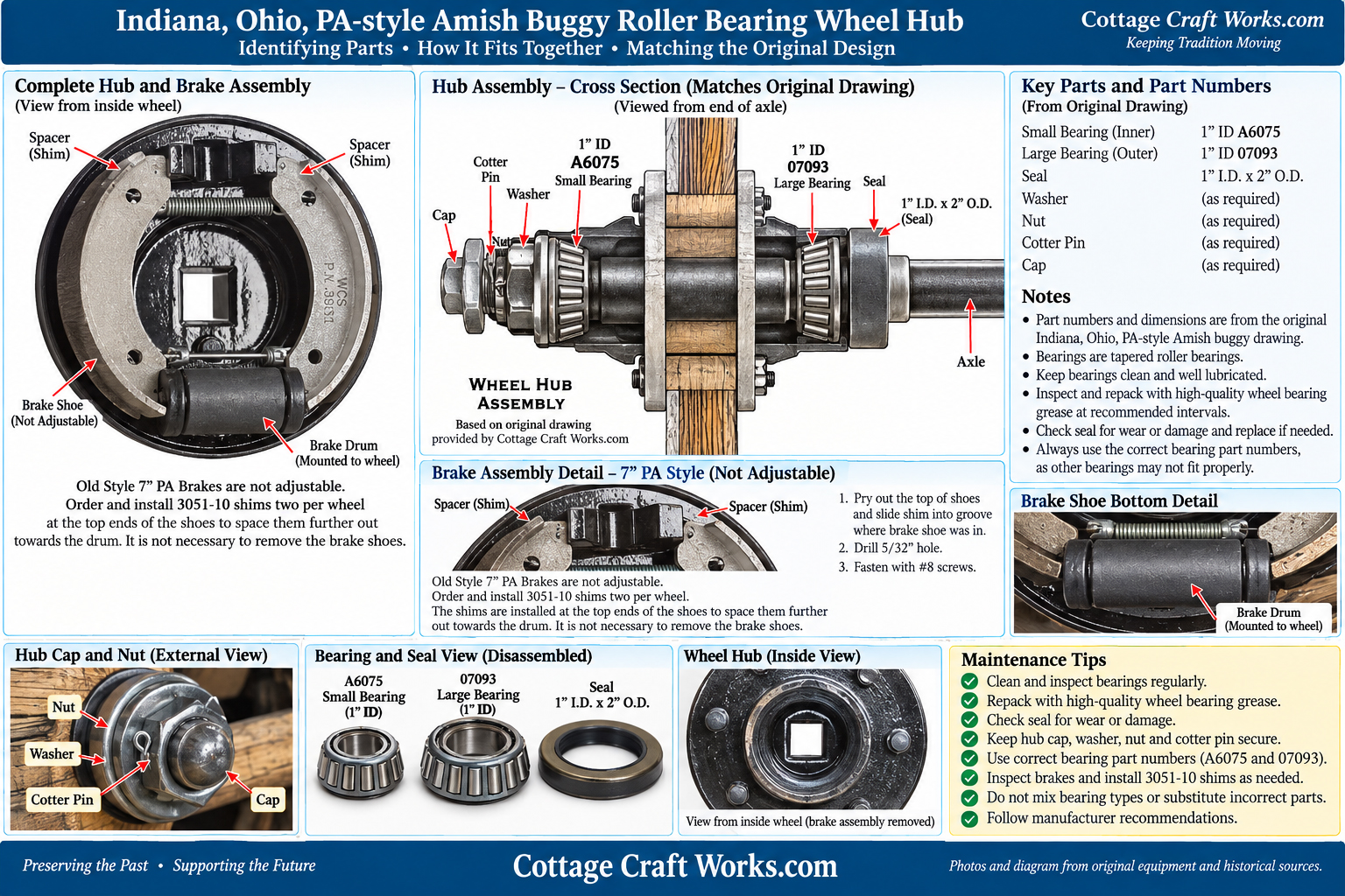
Indian, Ohio, PA-Style Amish Roller Bearing Wheel Hub
Downloads
- Download
Taperlock Brake Shoe Spring Installation and Brake Adjustment
- Download
Hydraulic Brake Troubleshooting and Performance Diagnosis
- Download
Taperlock Brake Bleeding and Master Cylinder Adjustment.
- Download
Taperlock Hydarulic Brake Manaual
- Download
Indian, Ohio, PA-Style Amish Roller Bearing Wheel Hub
Frequently Asked Questions
Do 7-inch and 8-inch Taperlock brakes use all the same parts?
What parts are inside the O-ring wheel cylinder?
What should be done after opening the hydraulic system?
Related Products
 Horse Carriage, Cart, Drum Brake Kit View product
 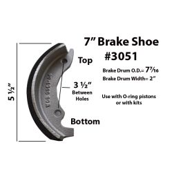 Horse-Drawn Vehicle Hydraulic Brake Shoes View product
 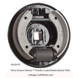 Horse Drawn Vehicle Brake Assembly View product
  Horse Drawn Vehicle Hydraulic Brake Master Cylinder View product
  Horse Drawn Vehicle Brake Components View product
  Horse Drawn Vehicle Brake Drum View product