
Article
How to Measure Well Depth, Select a Hand-Pump Cylinder & Plan a Safe Installation
How do I measure my well and select the correct lift cylinder for a deep-well hand pump?
First obtain the well record and verify the casing’s clear inside diameter, total depth, static water level and pumping water level at a known flow rate. Use drawdown and seasonal-low-water information to plan a cylinder setting that remains submerged but stays safely above the bottom and sediment. Then match the casing clearance, lift, desired output, handle effort, stroke, drop pipe and sucker rod to the pump manufacturer’s approved cylinder options. If the pipe string cannot be positively hoisted and supported throughout installation, use a qualified well or pump contractor.
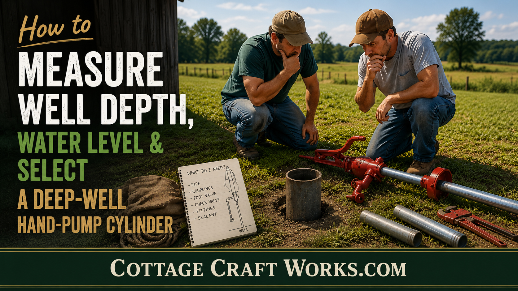
How to Measure Well Depth, Water Level & Select a Deep-Well Hand-Pump Cylinder
A practical planning and safety guide for deep-well hand pumps

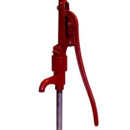
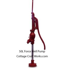
Deep-well hand-pump head and pipe components. Photograph supplied by Cottage Craft Works.
PLAN FIRST
The pump model is only one part of the system. Casing clearance, total well depth, static and pumping water levels, desired flow, cylinder depth, drop pipe, sucker rod, wellhead support, and safe lifting equipment must work together.
Before ordering a deep-well hand pump, gather reliable well measurements and decide how the complete suspended assembly will be installed and supported. This guide walks property owners through the measurements needed for pump and cylinder planning while identifying the point at which a qualified well or pump professional should take over.
Start With the Well Record
The safest and most accurate starting point is the well-completion or driller’s record. It may identify the casing diameter, total depth, screened or open-hole interval, static water level at the time of drilling, pump-test yield, grout, and casing details. Contact the original driller, state or county well-record office, local groundwater district, or a licensed well contractor before lowering improvised objects into an unknown well. Keep in mind that if the well was drilled many years ago, static water levels may have decreased over time due to area-wide population growth and extended drought conditions. Before moving forward, you may want to bring in a professional well company to pump down the well and measure its capacity and current static water levels. Keep in mind that most well companies will be working with submersible pump standards, which a hand pump will not draw down the well as quickly, so that should also be taken into consideration.
· Casing inside diameter and any reductions, liners, or obstructions
· Total completed depth and depth of the producing interval
· Static water level and date measured
· Pumping water level, test rate and duration
· Existing pump, wiring, pitless adapter, drop pipe or other equipment
· Water quality, sand, sediment, iron, or known corrosion conditions
Four Measurements That Are Often Confused
|
Measurement |
What it means |
Why it matters |
|
Total well depth |
Distance from the chosen reference point at the wellhead to the bottom of the completed well. |
Limits available installation space; it is not the same as lift. |
|
Static water level |
Depth from the reference point to water after the well has recovered and no pumping is occurring. |
Establishes the resting lift and available water column. |
|
Pumping water level |
Depth to water while pumping at a stated rate after the level stabilizes. |
Shows the operating lift the cylinder may actually face. |
|
Drawdown |
Pumping water level minus static water level. |
Shows how far the water level falls at the tested pumping rate. |
Choose and Record One Reference Point
Use one permanent, easy-to-relocate reference point—commonly the top edge of the casing or a marked point on the wellhead. Record whether measurements are taken from the top of casing or from ground level and record the casing height above grade. Mixing reference points can create a several-inch or even several-foot error in cylinder placement.

USDA Forest Service Figure 1: a complete hand-pump installation showing the stand, casing, drop pipe, pump rod, and cylinder. Public-domain U.S. Government work; reproduced for education. Source: Engineering Field Notes, Vol. 13, Jan.–Feb. 1981.
Measure the Casing Correctly
Measure the casing’s inside diameter whenever possible. Nominal casing size, outside diameter, and actual clear opening are not always identical. Account for liners, couplings, weld beads, pitless adapters, offsets, and existing equipment. The cylinder and every fitting that must pass through the wellhead need working clearance—not merely a theoretical diameter match.
|
Check |
Record |
|
Casing |
Material, nominal size, actual inside diameter and height above grade |
|
Restrictions |
Pitless adapter, liner, offset, reducer, weld, cable guard or damaged area |
|
Wellhead |
Opening diameter, mounting pattern, sanitary seal and structural support |
|
Shared use |
Whether an electric submersible pump, wire or pipe will remain in the casing |
IMPORTANT: Never assume that a cylinder sized exactly to the nominal casing diameter will pass through the well. Confirm the entire insertion path and the manufacturer’s required clearance.
How to Measure Static Water Level
An electric water-level meter is generally the cleanest and most practical method. Its narrow probe is lowered through a safe access opening until a light or buzzer indicates contact with water. Read the marked cable at the chosen reference point. Oklahoma State University Extension identifies metal tape, electric sounding devices and pressure transducers as common methods and describes the electric sounder as practical and effective.
1. Turn off all pumps using the well and allow adequate recovery time. Note the recovery period.
2. Confirm that the access path is clear of wiring, moving equipment, and obstructions. Never work through an unsafe energized wellhead.
3. Test the meter in suitable water before use, then lower the clean probe slowly.
4. At the first repeatable indication of water contact, read the cable at the established reference point.
5. Raise and repeat the measurement. Record the result, date, time, reference point, and whether nearby wells were pumping.
Do not use a loose weight on string where it could detach or become lodged. Do not lower a metal tape or probe alongside energized or operating equipment unless the equipment and access arrangement are specifically designed for safe measurement.
Measure Pumping Water Level and Drawdown
Static level alone does not indicate where the water will be while the pump is running. A pumping-level test records the water level at a known discharge rate after pumping long enough to observe whether the level stabilizes. Because a hand pump may be planned for a different rate than an existing powered pump, treat an old pump-test number as useful evidence—not a guarantee of current hand-pump performance.
Formula: Drawdown = pumping water level − static water level
Example: Static water level 58 ft; pumping water level 82 ft at 5 GPM; drawdown = 24 ft at that test condition.
If the well’s sustainable yield is unknown, the pumping level does not stabilize, the well produces sand, or the available records conflict, use a qualified well professional to conduct or interpret a yield test.
Select Cylinder Setting Depth—Not Just “Well Depth”
A deep-well cylinder must remain submerged during expected operating conditions and seasonal low-water periods, while staying above the well bottom and out of sediment. The correct setting is based on the pumping water level, drawdown behavior, historic drought or seasonal variation, producing interval, well construction, manufacturer requirements and local rules. A deeper setting increases the weight and friction of the rod-and-pipe system, thereby increasing installation difficulty.

USDA Forest Service Figure 2: typical reciprocating pump cylinders with piston, leathers and check valve. Public-domain U.S. Government work; reproduced for education. Source: Engineering Field Notes, Vol. 13, Jan.–Feb. 1981.
Cylinder Diameter, Stroke and Expected GPM
Cylinder bore affects displacement per stroke. A larger cylinder can move more water per stroke, but requires greater handle force at the same lift and may not fit the casing. A smaller cylinder reduces displacement but can be more manageable at greater lifts. Actual output is lower than theoretical displacement because of valve losses, leakage, incomplete stroke, rod stretch, operating speed, and wear.
Theoretical displacement: gallons per stroke = π × bore² × stroke ÷ (4 × 231), with bore and stroke in inches.
|
Cylinder bore |
12-in. theoretical gal/stroke |
At 30 strokes/min* |
At 40 strokes/min* |
|
1½ in. |
0.092 |
2.75 GPM |
3.67 GPM |
|
1¾ in. |
0.125 |
3.75 GPM |
5.00 GPM |
|
2 in. |
0.163 |
4.90 GPM |
6.53 GPM |
|
2¼ in. |
0.207 |
6.20 GPM |
8.26 GPM |
|
2½ in. |
0.255 |
7.65 GPM |
10.20 GPM |
|
3 in. |
0.367 |
11.02 GPM |
14.69 GPM |
*Theoretical only, assuming a full 12-inch piston stroke and no losses. Do not use this table as a performance promise or as a substitute for the current pump manufacturer’s cylinder-size, lift, stroke, force, and output data.
The casing diameter answers the question of “what may physically fit.” The pump model, lift, handle leverage, operator capability, desired delivery rate, and manufacturer’s approved combinations answer “what should be installed.”
Historical USDA Cylinder-Sizing Illustration

Historical USDA Forest Service installation drawing and cylinder-sizing guide for the specific hand-pump configuration shown. Public-domain U.S. Government work; reproduced for historical and educational reference. Source: Engineering Field Notes, Vol. 13, Jan.–Feb. 1981.
HISTORICAL REFERENCE ONLY: The cylinder sizes, rod, drop-pipe, and wellhead details shown belong to the pump system covered by the 1981 Forest Service drawing. Do not apply that chart automatically to a Heller-Aller 50L, 190-A, 192-A, or another pump. Use the current manufacturer’s instructions and verified site conditions.
Build a Pump-Selection Worksheet
|
Planning item |
Your well / requirement |
|
Well location and well-record number |
______________________________ |
|
Measurement reference point |
______________________________ |
|
Casing nominal size / actual clear ID |
______________________________ |
|
Total well depth |
______________________________ ft |
|
Static water level / date / recovery time |
______________________________ ft |
|
Pumping water level / test rate / duration |
____________ ft at ______ GPM |
|
Expected seasonal-low water level |
______________________________ ft |
|
Proposed cylinder setting |
______________________________ ft |
|
Desired delivery at wellhead |
______________________________ GPM |
|
Pump model and approved cylinder |
______________________________ |
|
Drop pipe / sucker rod / section length |
______________________________ |
|
Planned lifting and positive support method |
______________________________ |
|
Installer / contractor |
______________________________ |
Shallow-Well Work Is Not Deep-Well Work
Installing a light suction pump on a cistern or shallow well is fundamentally different from installing a deep-well force pump. A deep-well system may suspend a cylinder, many sections of water-filled drop pipe, sucker rod, couplings and fittings. During installation or removal, the crew must repeatedly support the entire suspended string while another section is raised, aligned and connected.
A Heller-Aller 50L at approximately 200 feet should not be described as a basic plumbing project. Long sections may stand vertically above the casing while the assembly below is suspended. A released pipe string can injure a worker, damage threads or casing, or drop pipe, rod and cylinder into the well—creating an expensive recovery job.
Using a Cottage Craft Works Pump Slide
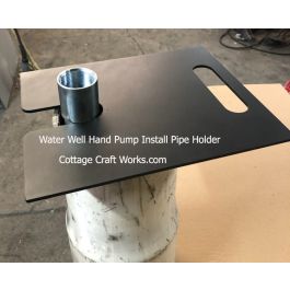
Cottage Craft Works carries a relatively inexpensive, simple pump slide designed to fit around the drop pipe below a pipe coupling or connector. Resting on the top of a suitable well casing, it helps hold the installed pipe string while the next pipe section is positioned and connected. This can make sectional pipe work more controlled and reduce reliance on workers trying to hold the suspended string by hand.
· Verify that the slide is correctly sized for the actual pipe and that the coupling or connector cannot pass through it.
· Verify that the casing top and wellhead structure can safely carry the full suspended load without slipping, tipping, cracking or deforming.
· Seat and inspect the slide before releasing any lifting tension. Keep hands and feet out of pinch and drop zones.
· Use a secondary retention or lifting method whenever the manufacturer’s procedure or the job conditions call for one.
The pump slide is a pipe-support aid—not a hoist, crane, fall-arrest device, engineered lifting plan or substitute for trained personnel. It does not control a long upper section standing in the air, and it cannot make an overloaded or poorly planned installation safe.
Know When to Call a Professional
Stop and arrange for a qualified well or pump contractor when any of the following applies:
· There is no positive, rated method to hoist and support the full suspended assembly at every stage.
· Long pipe or rod sections cannot be raised, stabilized, and aligned without workers standing beneath or beside an uncontrolled load.
· The installation is deep or heavy enough that manual control is uncertain—especially a substantial 50L installation approaching 200 feet.
· Existing joints are corroded, seized, or require large pipe wrenches and high torque to separate.
· The casing contains a submersible pump, wiring, pitless adapter, liner, offset, or other obstruction.
· Well depth, pumping level, yield, structural condition, or cylinder clearance is uncertain.
· Local law requires a licensed well contractor, permit, inspection, or sanitary wellhead work.
A professional may use a pump hoist, derrick, crane, or other suitable lifting system; positive pipe clamps or slips; properly sized pipe wrenches; tag lines and controlled work zones; and personnel experienced in suspended pump columns. The equipment must match the actual load and site.
Sanitary Work After the Well Is Opened
Keep pipe, rods, tools, and cylinder components clean and off the ground. Protect the casing opening from debris and surface water. After installation or repair, open the water system and follow current state or local requirements for disinfection, flushing, and bacteriological testing. University of Georgia Extension recommends shock chlorination when a well system is opened for installation, repair, or maintenance, but the correct procedure depends on well volume, materials, water chemistry, and local guidance.
Sources and Illustration Credits
· USDA Forest Service, Engineering Field Notes, “Hand Pump Operation and Maintenance,” Vol. 13, Jan.–Feb. 1981. Public-domain U.S. Government work. https://www.fs.usda.gov/eng/pubs/pdfpubs/pdf81713801/pdf81713801.pdf
· USDA Forest Service, Operation and Maintenance Manual for Hand Pumps, Technology & Development Program, 1999. https://www.fs.usda.gov/t-d/pubs/pdf/99231209.pdf
· Oklahoma State University Extension, “Measuring Depth to Groundwater in Irrigation Wells.” https://extension.okstate.edu/fact-sheets/measuring-depth-to-groundwater-in-irrigation-wells
· University of Georgia Cooperative Extension, “Disinfecting Your Well Water: Shock Chlorination.” https://fieldreport.caes.uga.edu/publications/C858-4/disinfecting-your-well-water-shock-chlorination/
· U.S. EPA, “Accuracy of Depth to Water Measurements.” https://www.epa.gov/sites/default/files/2015-06/documents/accur_depth_water.pdf
Disclaimer
This resource is for general educational and planning purposes only. It is not a site-specific engineering design, installation manual, lifting plan, safety program, water-quality directive or substitute for the current pump manufacturer’s instructions. Well construction, groundwater conditions, loads, equipment, codes, licensing and sanitation requirements vary. Verify all measurements and component compatibility before purchase or installation. Deep-well pump work involves suspended loads, pinch points, long pipe and rod sections, heavy tools, possible energized equipment and the risk of dropping equipment into the well. Use properly rated lifting and support equipment and qualified personnel. The Cottage Craft Works pump slide is a pipe-support aid only; it is not a hoist, crane, fall-arrest device or guarantee against slippage or equipment failure. Consult a licensed well or pump contractor and the appropriate state or local authority whenever conditions, procedures or legal requirements are uncertain. Cottage Craft Works and CCW LLC assume no responsibility for injury, contamination, property damage, equipment loss, well damage or other consequences arising from use or misuse of this information or any product.
Photos
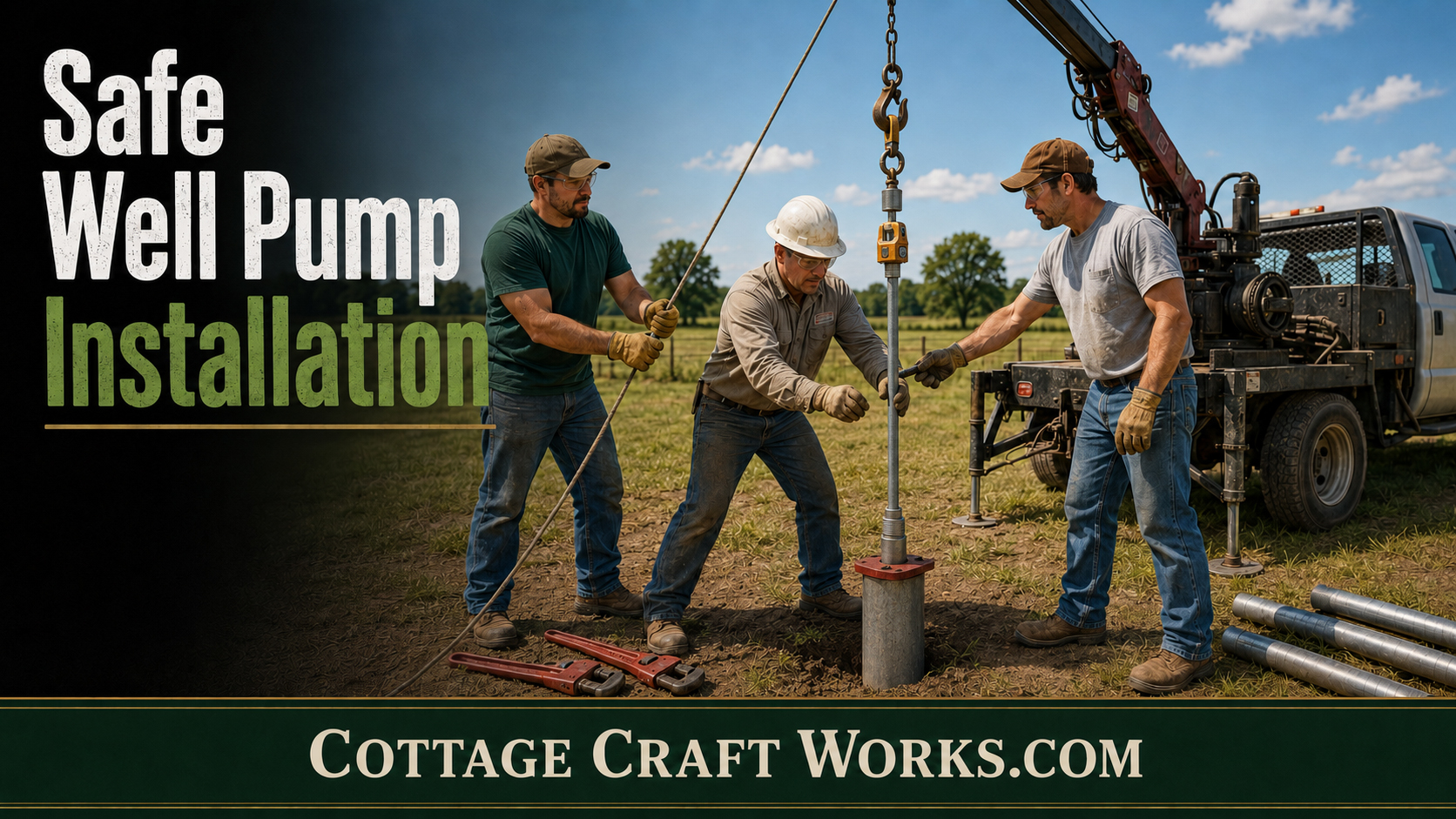
How to Safely Install a Hand Well Pump