
Article
Heller-Aller Model 192-A Installation & Adjustment Guide
How do you install and adjust a Heller-Aller Model 192-A Windmill Head Pump?
Install the brass cylinder below the pumping water level, support the drop pipe while adding centered rod sections, mount the pump squarely, align the windmill operating rod directly over the 192-A adapter, and adjust measured travel to a centered 4- or 6-inch stroke without bottoming the cylinder plunger.
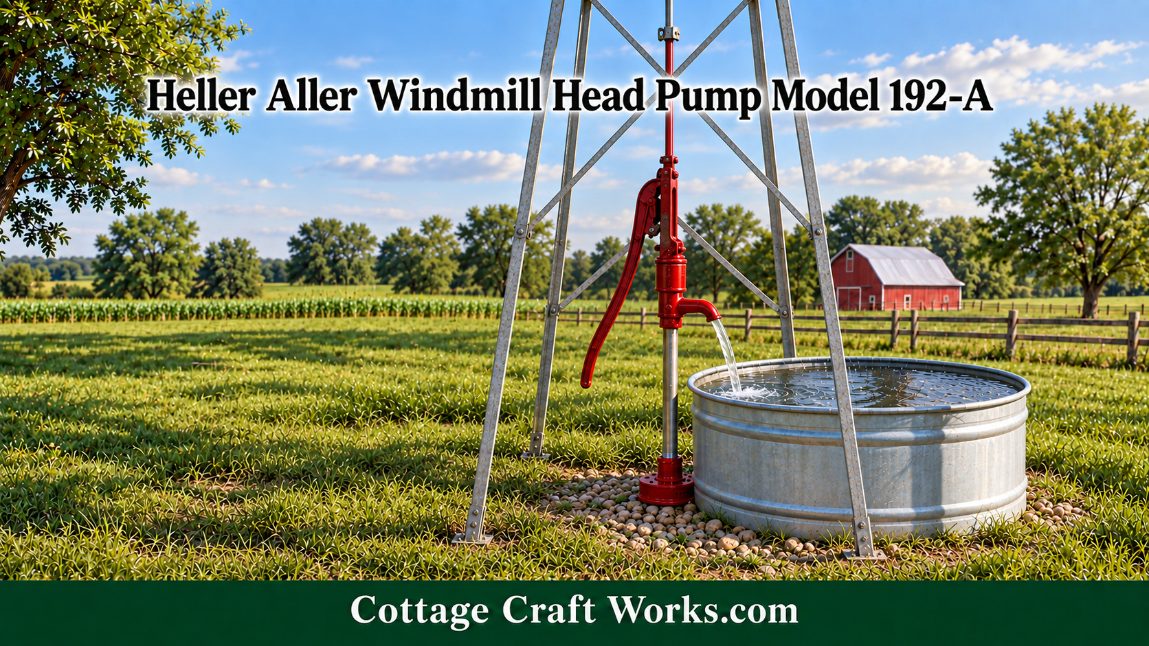
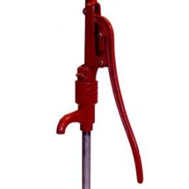
Model-specific installation and adjustment guidance for the Heller-Aller 192-A pump head, submerged brass lift cylinder, hand lever, windmill connector, and operating linkage.
The Model 192-A does its pumping at the submerged brass cylinder. Movement from the hand lever or windmill linkage travels through the stainless-steel rod to the cylinder plunger. The valves and plunger leather then lift water through the 1¼-inch drop pipe and discharge it through the open spout. For reliable operation, the cylinder must remain submerged, the pipe and rod must remain centered, and the windmill linkage must deliver a controlled stroke without pulling sideways or driving the plunger into either end of the cylinder.
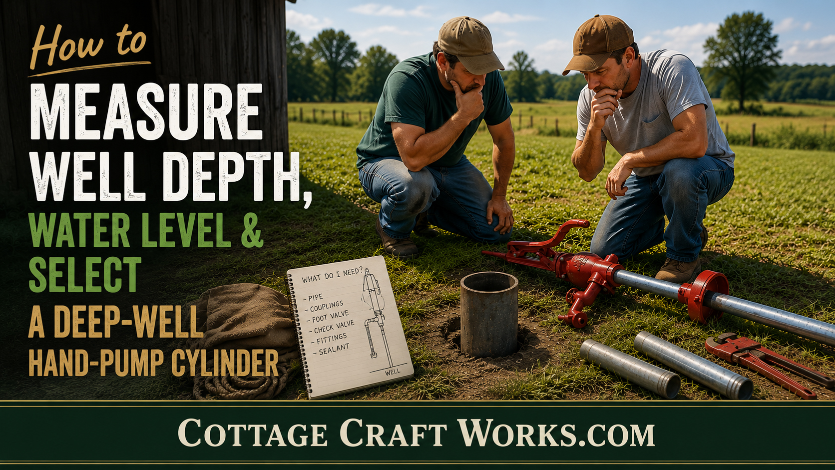
Use the existing Cottage Craft Works deep-well installation resources to measure the well, determine cylinder depth, select safe pipe-handling equipment, sanitize the system, and rebuild the brass cylinder. The procedure below concentrates on the 192-A pump head and windmill connection.
Before Installation
Record total well depth, static water level, expected pumping level after drawdown, casing diameter, frost depth, and clearance above sediment.
Confirm the selected flat platform, 4-inch, 6-inch, or optional 6-inch offset base.
Verify the 2½-inch × 10-inch brass cylinder, 1¼-inch pipe connection, stainless-steel rod, couplings, and optional windmill connector.
Inspect the windmill tower foundation, guide hardware, central operating rod, pivots, and shutdown system before connection.
Prepare a positive pipe-holding device and lifting method before suspending any assembly in the casing.
Keep all water-system components clean and protect open threads from soil and debris.
SAFETY NOTE: Never work on linkage while the windmill can move. Positively secure the wheel and mechanism before approaching the pump, rods, pins, guides, or tower base. Keep clear of suspended loads and pinch points. Use qualified well and windmill personnel whenever the assembly, tower condition, or working height cannot be controlled safely.
Cylinder, Drop Pipe & Pump Rod Installation
1. Determine cylinder depth. Place the cylinder below the anticipated pumping water level and drawdown while maintaining clearance above sand and sediment. A tailpipe may extend below the cylinder inlet. A foot valve is recommended for deeper installations.
2. Confirm cylinder orientation. Identify the outlet toward the pump and inlet toward the water source from the supplied parts or instructions. Do not assume the ends are interchangeable.
3. Connect the first rod and pipe. Attach the stainless-steel rod to the cylinder plunger connection. Thread the 1¼-inch drop pipe into the cylinder outlet using potable-water-rated sealing material, kept out of the waterway.
4. Lower controlled sections. Support the entire load with the drop pipe and a positive holding device at the casing—never with the pump rod. Add one pipe section and its matching rod section at a time, keeping both centered.
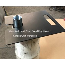
5. Finish at the well head. Support the drop pipe independently while positioning and fastening the selected base. Maintain a sanitary seal and protect wiring in an offset-cap installation.
Mount & Hand-Test the Pump Head
6. Position the pump head. Set the 192-A squarely over the drop pipe with the open spout directed toward the tank or discharge area. Do not place the pump where the tower or tank forces the rod out of line.
7. Connect the pump rod. Join the rod to the pump linkage without bending it. Remove excess slack while retaining clearance so the plunger does not contact an end fitting.
8. Select the initial stroke. Set the pump for a 4- or 6-inch stroke that matches the intended windmill travel and operating load. Begin conservatively when the windmill geometry has not yet been measured.
9. Test by hand. Operate the lever slowly through repeated strokes. Confirm free travel, consistent water delivery, and no scraping, knocking, side pull, or hard stop before adding windmill power.
Connect & Adjust the Windmill
10. Secure the windmill. Use the mill’s shutdown and a positive mechanical restraint so the wheel and operating mechanism cannot begin moving during the work.
11. Align the central rod. Position the 192-A directly below the windmill operating rod. The rod should descend vertically through the tower and remain centered over the pump adapter throughout the cycle.
12. Install the windmill connector. Attach the correct 192-A adapter and required pin, clevis, coupling, and retaining hardware. Joints should articulate freely without excessive looseness.
13. Measure actual travel. Move the windmill mechanism through one complete cycle by controlled manual means. Measure the pump-rod travel rather than estimating it from crank position or catalog stroke.
14. Set the 4- or 6-inch stroke. Adjust the windmill connection point or linkage geometry to produce the selected stroke without exceeding the pump’s permitted travel.
15. Center the stroke. At the top and bottom of the cycle, retain clearance so the cylinder plunger cannot strike either end. Correct rod length or the connection point before operation if the travel is not centered.
16. Begin in light wind. Release the mill only under controlled light-wind conditions. Observe several complete cycles and stop immediately for side motion, binding, hammering, loose hardware, tower vibration, or end-of-stroke impact.
Final Adjustment Checks
The windmill rod stays vertical and centered over the pump.
Pins, retainers, couplings, base fasteners, and guides remain secure.
The pump completes the measured stroke without bottoming.
Water delivery is steady at both hand and windmill speeds.
The pump holds the water column between strokes.
The spout discharges freely and is not connected to a closed-pressure system.
The well cap stays sealed and surface drainage moves away from the casing.
Routine Inspection & Seasonal Adjustment
Recheck stroke, alignment, guide wear, pins, fasteners, rod couplings, and tower movement after the first sustained run, after severe winds, and at regular service intervals. Lubricate only the points identified by the current manufacturer instructions, using the specified lubricant and keeping oil away from potable-water components.
The standard 4-foot set-length arrangement is described as anti-freezing when correctly installed. Confirm local frost depth and drainage. Ice at the spout, trapped water, inadequate burial, or a cylinder installed above protected depth can still cause damage.
After installation or internal service, disinfect and flush the well and pump system according to the Cottage Craft Works sanitation guidance and local requirements. Do not return the system to drinking-water service until disinfectant has been flushed and any required water testing is satisfactory.
Troubleshooting Adjustment Problems
Hard stop or hammering: Stop the windmill. Check for plunger bottoming, excessive stroke, incorrect rod length, loose linkage, or a misplaced connection point.
Side movement or rapid guide wear: Check tower geometry, pump placement, guide alignment, bent rods, and a connector that pulls the pump off center.
Low or intermittent delivery: Check cylinder submergence, drawdown, valves and leathers, pipe leakage, foot valve, inlet restriction, and inadequate stroke.
Pump loses prime: Inspect the cylinder valve, foot valve, pipe joints, and water level. Linkage adjustment alone will not correct a leaking water column.
Loose or noisy connection: Inspect clevis pins, retainers, bushings, couplings, guides, and mounting hardware before continued operation.
Disclaimer
This resource is for general educational and planning purposes only. It is not a site-specific engineering design, a replacement for the current manufacturer instructions, or a substitute for qualified well and windmill personnel. Conditions vary by well, tower, water level, casing, soil, weather, equipment condition, and local code. Cottage Craft Works LLC assumes no responsibility for injury, contamination, property damage, equipment loss, well damage, or other consequences arising from use of this information.
Source Notes
Model-specific dimensions, stroke options, depth range, and base choices are based on current Hitzer and Cottage Craft Works Model 192-A product information. Always follow the instructions supplied with the current pump, cylinder, base, and windmill connector.