
Article
How a Heller-Aller Fig. T Brass Cylinder Well-Cistern Pump Works
Question: How does a Heller-Aller Fig. T Brass Cylinder Well-Cistern Pump work?
A Heller-Aller Fig. T Brass Cylinder Well-Cistern Pump works by using the hand lever to move a plunger inside a brass cylinder. The plunger and one-way check valves create pressure changes that draw water up an airtight suction pipe from a cistern or shallow well. The valves help prevent the water from flowing backward between strokes, so repeated pumping progressively lifts the water until it discharges from the spout.
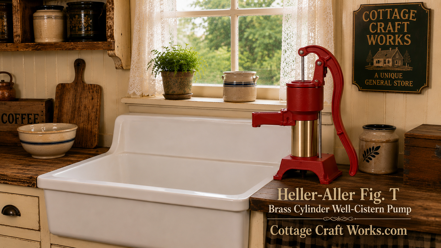
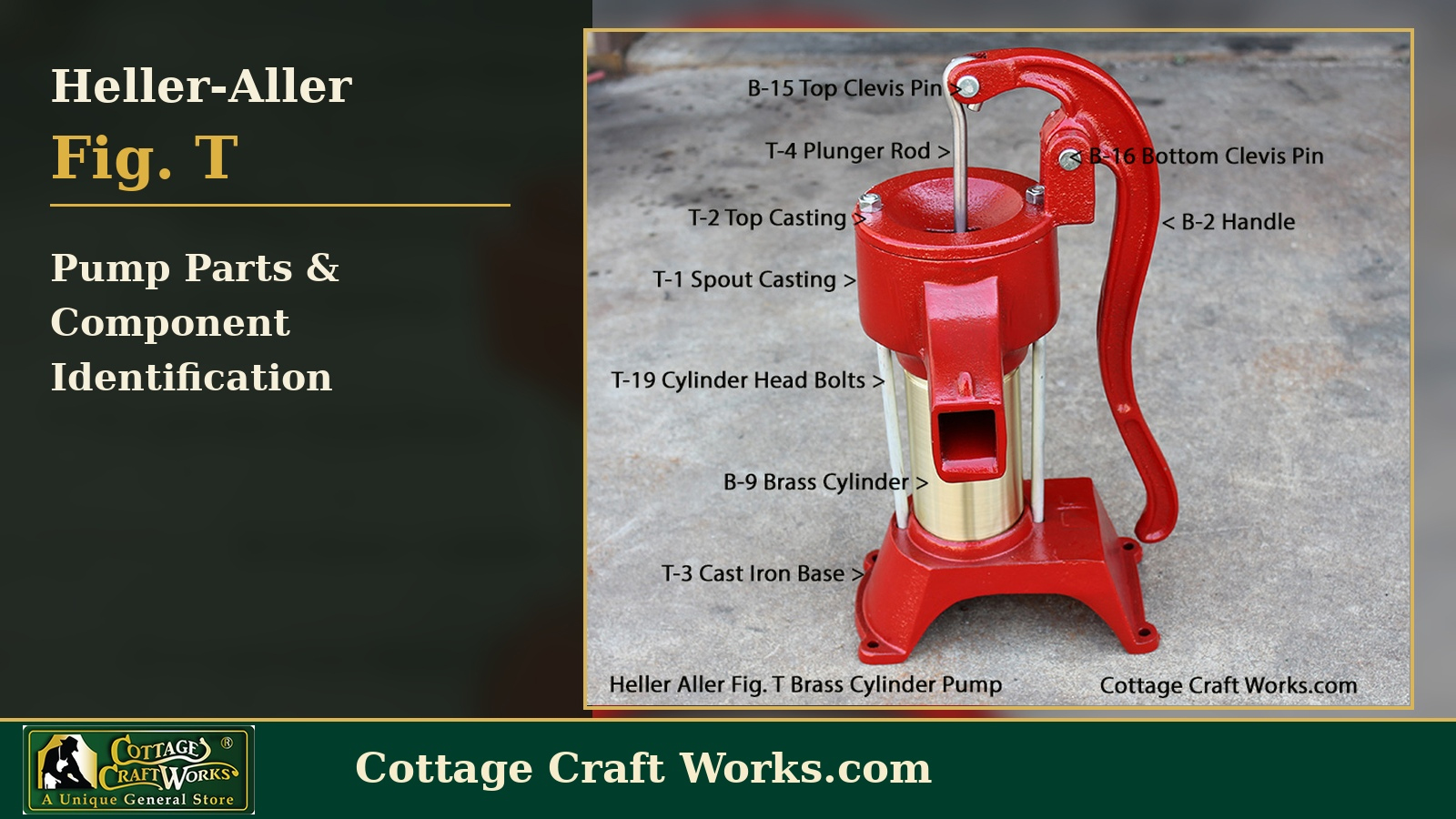
The Heller-Aller Fig. T Brass Cylinder Well-Cistern Pump is a manually operated suction pump designed to lift water from cisterns and shallow wells. Moving the handle operates an internal plunger. Check-valve action allows water to move upward through the pump while helping prevent it from flowing backward between strokes. The simple mechanical design requires no electricity and uses serviceable internal components that can be inspected and replaced as they wear.
The Heller-Aller Fig. T Brass Cylinder Well-Cistern Pump works by converting the up-and-down movement of its handle into a reciprocating motion within the pump cylinder. The pumping action creates pressure changes that allow water to be drawn from the source and moved upward toward the discharge spout.
At the heart of the pump is the brass cylinder. Inside the cylinder, a plunger moves as the handle is operated. The close working relationship among the cylinder, plunger, leather sealing components, and valves enables the pump to develop suction and move water.
The pump depends on one-way check-valve action. These valves are designed to open when water needs to move upward and close when the direction of pressure changes. By restricting backward flow, the valves allow each handle stroke to build on the water already lifted during the previous stroke.
When the handle is moved through a pumping stroke, the plunger changes the pressure inside the cylinder. This pressure difference helps draw water upward through the suction pipe from the cistern or shallow well. As the valve opens, water enters the pumping chamber.
During the opposite portion of the stroke, the valve arrangement changes. A check valve closes to prevent water from flowing back toward the source, while the plunger and its valve allow the next portion of water to move upward. Repeated handle strokes progressively raise the water until it reaches the pump body and flows from the discharge spout.
Because the Fig. T works on the suction principle, the vertical distance from the pump to the actual water level is critical. The important measurement is not simply the total depth of the cistern or well. It is the vertical lift from the water surface to the pump during operation.
Atmospheric pressure places a physical limit on how high a suction pump can lift water. Real-world performance is also affected by pipe size, fittings, air leaks, valve condition, leather condition, and installation quality. For this reason, the Fig. T is intended for cistern and shallow-well applications rather than deep-well installations.
A suction-side air leak can prevent the pump from working even when the internal components are in good condition. The suction pipe and fittings must therefore remain airtight. Small leaks that might not visibly leak water can still allow enough air into the system to interfere with priming and suction.
The leather seals and valve components are wear items. As leather dries, hardens, shrinks, or becomes damaged, the pump may lose its ability to seal effectively. Valve wear or debris can also allow water to leak backward between strokes, resulting in reduced flow, difficulty priming, or loss of prime.
This is one of the advantages of the traditional Fig. T design. Instead of relying on an electric motor or a sealed disposable assembly, the pump uses serviceable mechanical components that can be inspected, cleaned, adjusted, and replaced as needed.
Understanding the pumping cycle is especially useful when troubleshooting. If the handle moves but little or no water reaches the spout, the problem can often be narrowed to a few areas: loss of prime, excessive suction lift, an air leak in the suction line, a worn leather seal, a valve that is not seating properly, or an obstruction in the water path.
For owners who are maintaining an older pump or installing a new one, understanding how the Heller-Aller Fig. T works is essential for proper installation and repair. Once the relationship between the handle, plunger, valves, seals, cylinder, suction pipe, and water level is understood, diagnosing most common pumping problems becomes much easier.
Cottage Craft Works provides Heller-Aller pumps, replacement parts, and educational resources to help owners identify components, plan installations, troubleshoot pumping problems, and rebuild traditional hand-operated water systems.
Disclaimer
This information is provided for general educational purposes. Always follow the manufacturer's instructions and observe appropriate safety practices for pump and piping installations.