


Article
Heller-Aller Fig. T Brass Cylinder Pump Rebuilding & Leather Replacement Guide
How do you rebuild a Heller-Aller Fig. T Brass Cylinder Pump and replace the pump leathers?
Rebuilding a Heller-Aller Fig. T Brass Cylinder Pump involves disassembling the brass-cylinder assembly, removing and inspecting the plunger, cleaning and examining the B-9 brass cylinder, and inspecting the cage, follower, poppet, valve weight, rod, and linkage. Worn leather components are replaced with the CL 300 cup leather, LV 275 valve leather, and 708 leather gasket. The new cup leather should be made pliable before installation, carefully installed in the plunger assembly, and guided into the clean brass cylinder without folding or damaging its sealing edge. The valve leather must be installed against a clean valve-seating surface. After reassembly, the pump is primed and operated until the new leathers become fully wetted and establish a dependable seal. If the rebuilt pump still will not draw water, check the suction pipe for air leaks, verify that the water level is within the Fig. T's approximately 20-foot suction-lift capability, and inspect valve seating before disassembling the pump again.
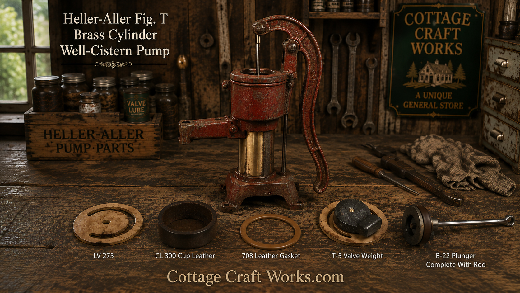
The Heller-Aller Fig. T Brass Cylinder Pump was designed to be repaired rather than discarded when normal wear reduces pumping performance. The primary wear components are the leather seals that allow the plunger and valves to create suction and move water through the brass cylinder.
A Fig. T that has become difficult to prime, produces less water, loses its prime, or has been sitting unused for many years may simply need inspection, cleaning, and replacement of its cup leather, valve leather, and gasket rather than replacement of the entire pump.
Rebuilding a Heller-Aller Fig. T Brass Cylinder Pump
One of the advantages of the Heller-Aller Fig. T is its relatively simple, serviceable construction. Unlike many modern pumps designed around disposable assemblies, the Fig. T uses a brass cylinder, mechanical plunger assembly, and replaceable leather seals.
The surviving Heller-Aller factory parts literature identifies the major service components, including the B-9 Brass Cylinder, T-6 Plunger Complete with Rod, B-10 3-inch Cage, B-11 3-inch Follower, B-12 3-inch Poppet, B-17 LV 275 Leather, B-18 CL 300 Leather, and B-20 708 Leather Gasket.
Cottage Craft Works currently supplies the three leather components together as a Fig. T leather replacement kit.
When Should a Fig. T Pump Be Rebuilt?
Consider rebuilding the pump when it:
- Will not prime even though the suction line is airtight and the water level is within the pump's operating range.
- Requires excessive pumping before water appears.
- Pumps noticeably less water than it once did.
- Loses its prime unexpectedly.
- Has little resistance when the handle is operated.
- Has dried, cracked, hardened, distorted, or damaged leather components.
- Has been unused or stored dry for an extended period.
- Has been disassembled for restoration and the condition of the internal wear components is unknown.
Before rebuilding the pump, verify that the problem is actually inside the pump. An air leak in the 1¼-inch suction pipe, an excessively low water level, or a leaking fitting can produce symptoms similar to worn pump leathers.
Before Disassembly
If possible, photograph the pump and its components before and during disassembly.
Older pumps may have been repaired several times during their working life, and parts may have been replaced, modified, or installed differently. Photographs provide a valuable reference during reassembly.
Clean dirt and debris from the outside of the pump before opening it so contamination does not enter the brass cylinder.
If the pump supplies drinking water, keep all internal parts, tools, work surfaces, and replacement components clean.
Step 1 — Remove the Pump From Service
Disconnect the pump from its water supply or otherwise place the system in a condition where it can be safely serviced.
If the Fig. T is permanently mounted, determine whether the repair can conveniently be performed in place or whether removing the pump from the mounting surface will provide better access.
Do not allow loose parts or debris to fall into an open suction pipe or cistern.
Step 2 — Inspect the Handle, Pins and Plunger Rod
Before opening the cylinder, inspect the external operating mechanism.
Check the:
- Handle
- Pivot points
- Clevis pins
- Plunger rod
- Connections between the handle and rod
- Top casting
Excessive looseness in the linkage can reduce effective plunger travel even when the internal leathers are still serviceable.
The original Fig. T parts literature identifies the B-2 Handle, T-4 Plunger Rod, B-15 and B-16 Clevis Pins, along with the T-1 and T-2 upper castings.
A badly worn, bent, rough, or corroded plunger rod should be corrected before new leather components are expected to provide proper service.
Step 3 — Open the Brass Cylinder Assembly
Carefully disassemble the pump sufficiently to expose the B-9 brass cylinder and plunger assembly.
The Fig. T uses two long B-19 3/8-inch × 11-inch bolts as part of the cylinder assembly.
Loosen hardware evenly rather than placing unnecessary stress on one side of the castings.
Older cast iron can be damaged by excessive force. If components are stuck from age, corrosion, or mineral deposits, work patiently rather than attempting to force the casting apart.
Keep hardware organized in the order it was removed.
Step 4 — Remove the Plunger Assembly
Carefully withdraw the plunger and rod from the brass cylinder.
Avoid dragging sharp hardware across the inside surface of the cylinder.
Once removed, inspect the complete plunger before taking it apart. Note the position and orientation of the:
- Cage
- Follower
- Poppet
- Cup leather
- Rod
- Retaining components
The original Heller-Aller parts list identifies the complete assembly as the T-6 Plunger Complete with Rod.
Step 5 — Inspect the B-9 Brass Cylinder
The condition of the B-9 brass cylinder is important because the cup leather must maintain contact with its inner wall to produce effective pumping action.
Clean the cylinder and inspect the interior for:
- Mineral deposits
- Dirt or sediment
- Heavy scoring
- Grooves
- Corrosion
- Dents
- Out-of-round areas
- Sharp edges that could damage a new leather
Minor staining or normal polishing from use does not necessarily make the cylinder unusable.
The important question is whether the cylinder provides a reasonably smooth, continuous sealing surface for the cup leather.
Do not aggressively grind or remove significant material from the brass cylinder simply to make it look new.
Step 6 — Inspect the Existing Cup Leather
The CL 300 cup leather forms the working seal between the plunger and the inside wall of the brass cylinder.
A serviceable leather should remain sufficiently flexible to conform to the cylinder wall.
Replace it if it is:
- Hard or brittle
- Cracked
- Torn
- Badly worn
- Permanently distorted
- Missing sections
- Unable to expand against the cylinder wall
A dried leather may sometimes soften after being wetted, but an old leather that has deteriorated should be replaced rather than depended upon for a drinking-water pump.
Step 7 — Disassemble the Plunger and Replace the CL 300 Cup Leather
Cottage Craft Works' Fig. T parts information specifies that the follower must be removed from the cage assembly to replace the cup leather. The assembly can be inverted, and the cage carefully held while a large wrench is applied to the flat sides of the follower. The cage should not be crushed or overtightened in the vise because the casting can crack. If the cage is rusted on, hold it in one hand with the stem and the follower up. Tap the bottom of the follower with a hammer to knock it loose. Do not place the stem on a solid surface or place it in a vice to hold it while tapping it, as this will break the cage. Holding it in one hand provides enough bounce for the shock to radiate to the other hand.
Remove the follower and old CL 300 cup leather.
Clean the mating surfaces and inspect the cage, follower, poppet, and threads.
Install the new CL 300 cup leather in the same functional orientation as the original factory assembly.
Do not force a stiff, dry leather into the brass cylinder.
Tip: The cage can be difficult to remove if the pump has sat and rusted. It is easier to remove when it is wet. Hold the stem upright in one hand and take a hammer and smack it to loosen it. It is important not to clamp the stem in a vice or sit the stem on a solid surface and smack it, as that will break the casting. Holding it in one hand softens the blow.
Preparing a New Cup Leather
New leather should be made pliable before it is forced into the cylinder. General hand-pump service guidance recommends wetting or conditioning the leather before installation so it conforms to the cylinder and establishes a seal.
For a potable-water pump, avoid automotive oils, petroleum grease, or other lubricants that are not intended for drinking-water equipment.
Clean water can be used to soften the leather before assembly. If a lubricant is required, use only one specifically suitable for potable-water equipment and compatible with leather.
Step 8 — Reassemble the Plunger
Reinstall the cup leather, follower, poppet, cage, and related components in their proper order.
The original Fig. T parts identification lists:
B-10 — 3" Cage
B-11 — 3" Follower
B-12 — 3" Poppet
B-18 — CL 300 Leather
These components work together as the plunger assembly.
Tighten the assembly securely enough to retain the components without unnecessarily crushing or deforming the new leather.
After assembly, verify that the cup leather is centered and uniformly positioned.
Step 9 — Inspect and Replace the LV 275 Valve Leather
The LV 275 leather is the flat valve leather used in the lower valve assembly.
Unlike the cup leather, which seals against the brass cylinder wall, the valve leather operates as part of the pump's one-way water-control system.
Inspect it for:
- Cracking
- Hardening
- Curling
- Tears
- Distortion
- Mineral buildup
- Damage around the openings
- Failure to lie correctly against its sealing surface
Replace a damaged or hardened valve leather.
Clean the valve seating surfaces before installing the new leather. Old leather fragments, mineral deposits, rust scale, or other debris can prevent the valve from sealing even when a new leather is installed.
General hand-pump repair guidance likewise emphasizes cleaning the valve seat and installing the new valve leather flat and properly positioned.
Step 10 — Inspect the Valve Weight, Poppet and Follower
Do not automatically assume that replacing the leather will correct every valve problem.
Inspect the metal components that support and control the leather.
The Fig. T factory literature identifies the:
T-5 Valve Weight
B-11 Follower
B-12 Poppet
as individual service components.
Look for corrosion, distortion, mineral buildup, excessive wear, or damage that could prevent the valve from moving or seating correctly.
Clean reusable parts before reassembly.
Step 11 — Replace the 708 Leather Gasket
The Fig. T leather kit also includes the 708 leather gasket, identified in the factory parts list as B-20.
Whenever the pump is substantially disassembled for rebuilding, inspect this gasket carefully.
Replace it if it is compressed beyond reuse, brittle, torn, distorted, or no longer capable of providing a dependable seal.
Clean both gasket-contact surfaces before installing the replacement.
Do not attempt to compensate for a damaged gasket by excessively tightening the castings.
Step 12 — Inspect the Brass Cylinder Before Final Assembly
Before inserting the rebuilt plunger, wipe the inside of the cylinder clean once more.
There should be no:
- Loose scale
- Sand
- Metal particles
- Pieces of old leather
- Cleaning residue
- Sharp debris
Wet the new cup leather with clean water before inserting it.
Carefully guide the edge of the cup into the cylinder rather than forcing it against the cylinder opening. A folded, rolled, or cut cup leather may fail immediately even though it is new.
Step 13 — Reinstall the Plunger Assembly
Carefully slide the rebuilt plunger into the B-9 brass cylinder.
Some resistance is normal because the cup leather must contact the cylinder wall to create a seal.
However, the plunger should not require extreme force.
If it binds badly, stop and inspect the leather rather than forcing the assembly farther into the cylinder.
Check that the rod remains centered and moves without scraping or binding.
Step 14 — Reassemble the Pump
Reassemble the Fig. T in the reverse order of disassembly.
Align the top casting, brass cylinder, base, long cylinder bolts, rod, linkage, and handle before final tightening.
Tighten the long cylinder hardware evenly from side to side so the castings seat uniformly against the cylinder and gasket.
Do not use excessive torque on old cast-iron components.
Operate the handle slowly by hand before reconnecting the water supply. The rod and plunger should travel smoothly through the complete stroke.
Step 15 — Prime the Rebuilt Pump
After rebuilding, the Fig. T will normally require priming.
Pour clean water into the pump while operating the handle until the cylinder fills and the pump begins drawing water.
Continue operating the pump until a steady stream flows from the spout.
New leather components may require a short period of operation and water exposure before they fully conform to their mating surfaces.
Step 16 — Test the Rebuilt Pump
Once the pump is delivering water, check for:
- Smooth handle movement
- Normal pumping resistance
- Steady water delivery
- Leakage around the cylinder or gasket
- Leakage at pipe connections
- Unusual mechanical noises
- Binding of the rod or linkage
- Loss of prime after the pump sits
Allow the new leathers time to become completely wetted and seated before concluding that an adjustment or another repair is necessary.
If the Rebuilt Fig. T Still Will Not Pump
If new leathers have been installed correctly but the pump still will not draw water, check the entire installation before disassembling it again.
Look for:
- Air leaks in the suction pipe or fittings
- Water level beyond the pump's approximately 20-foot suction-lift capability
- Improper priming
- Incorrectly installed or damaged cup leather
- LV 275 valve leather not seating properly
- Dirt or debris beneath a valve
- Damaged gasket or leaking cylinder joint
- Worn or damaged plunger components
- Excessive linkage or clevis-pin wear
- Damaged or heavily scored brass cylinder
A suction-side air leak can prevent a perfectly rebuilt pump from lifting water.
Long-Term Care of Fig. T Pump Leathers
Leather pump components last longest when the pump is used periodically and the leathers are allowed to remain conditioned by water.
If a pump sits unused for a long period, the leather may dry and shrink. The pump may then require additional priming before it begins working normally again.
Avoid introducing petroleum oils or unapproved chemicals into a pump supplying drinking water.
If freezing conditions are possible, follow the Fig. T draining procedure by raising the handle fully and holding it up for approximately 10 seconds, allowing the lower valve to open so water can drain from the pump and supply line.
Sanitizing After Rebuilding
If the Fig. T supplies drinking water, sanitize the pump and the connected water system after rebuilding and before returning it to potable water service.
Use an approved well or cistern disinfection procedure and operate the pump until chlorinated water has passed through the internal pump components and spout. After the required contact time, thoroughly flush the system with clean water before drinking.
Cottage Craft Works Note: The amount of chlorine required depends upon the type and volume of the water system. Do not use a single fixed bleach quantity for every well or cistern installation.
Disclaimer
This information is provided for general educational purposes. Always follow the manufacturer's instructions and observe appropriate safety practices for pump and piping installations.
Photos
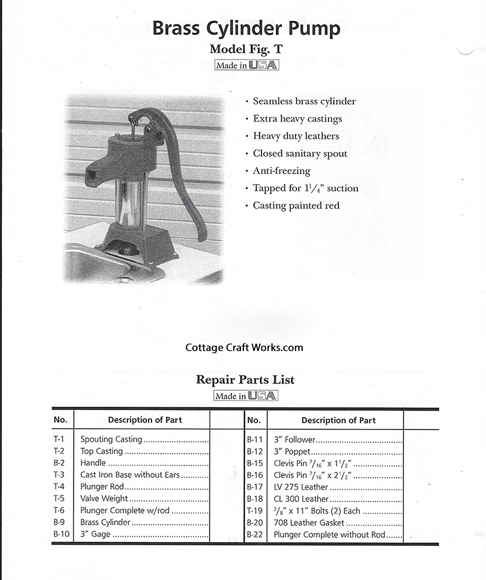
Heller Aller Fig T Pump Parts Listing 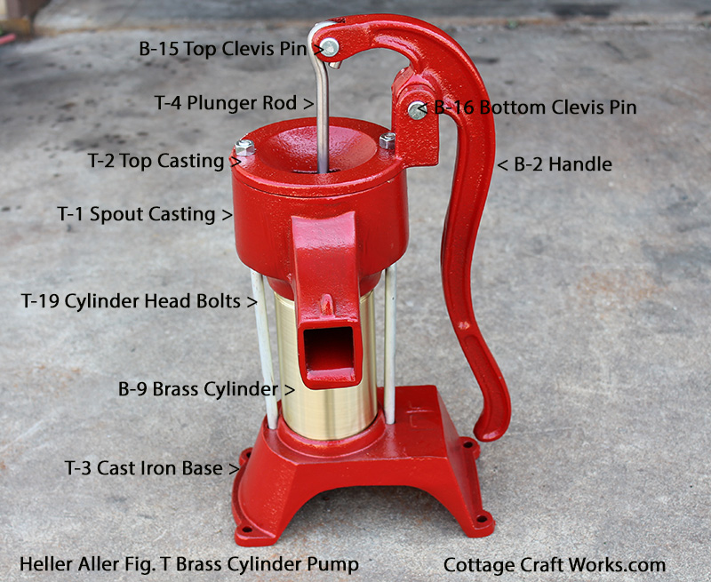
Heller Aller Fig T Pump Parts ID 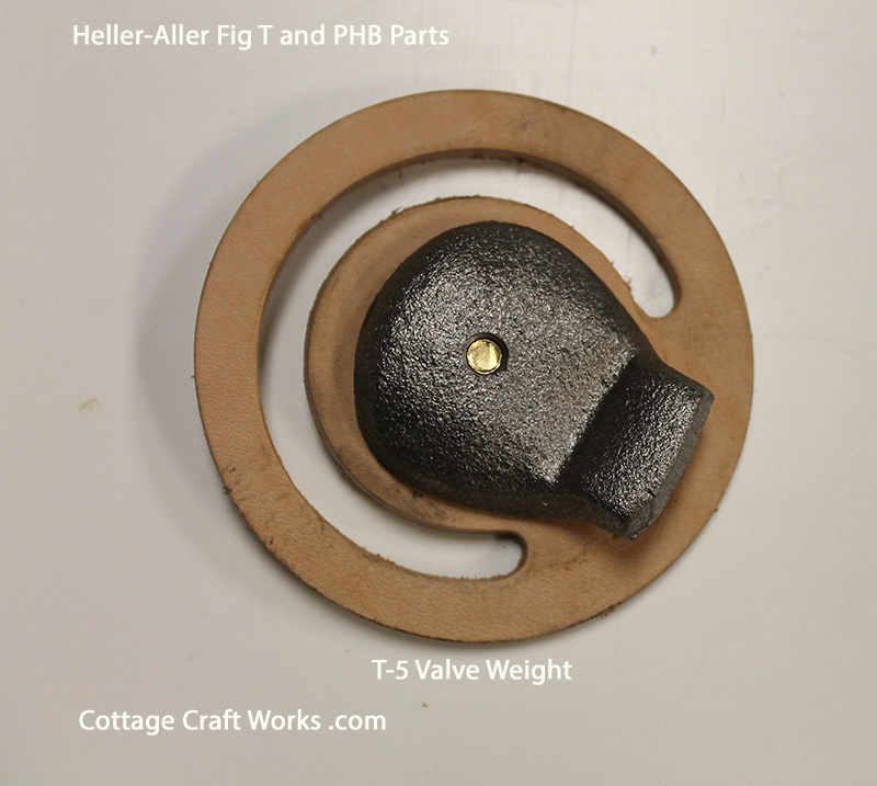
Fig T LV275 Lower Leathe and T-5 Valve Weight 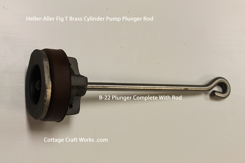
Fig T Complete Plunger 
Fig T Brass Cylinder 
Fig T Pump Leather
