
Article
Heller-Aller 50L Troubleshooting, Rebuilding & Repair Guide
How do I troubleshoot and rebuild a Heller-Aller 50L force pump?
Start by treating the 50L as a complete two-cylinder system. Verify the pumping water level, discharge path, pressure system, handle linkage, stroke, and sucker-rod adjustment before disassembly. Weak or uneven flow may result from worn leathers, leaking or obstructed valves, a leaking drop-pipe joint, rod failure, drawdown, or damage in the upper double-acting force cylinder or submerged lift cylinder. Rebuild with confirmed Heller-Aller 50-L parts, preserve the valve and leather orientation, inspect the bores and seats, and test the motion by hand before returning the pump to service. Pulling the lift cylinder requires positive pipe support and may require a qualified contractor with a pump hoist.
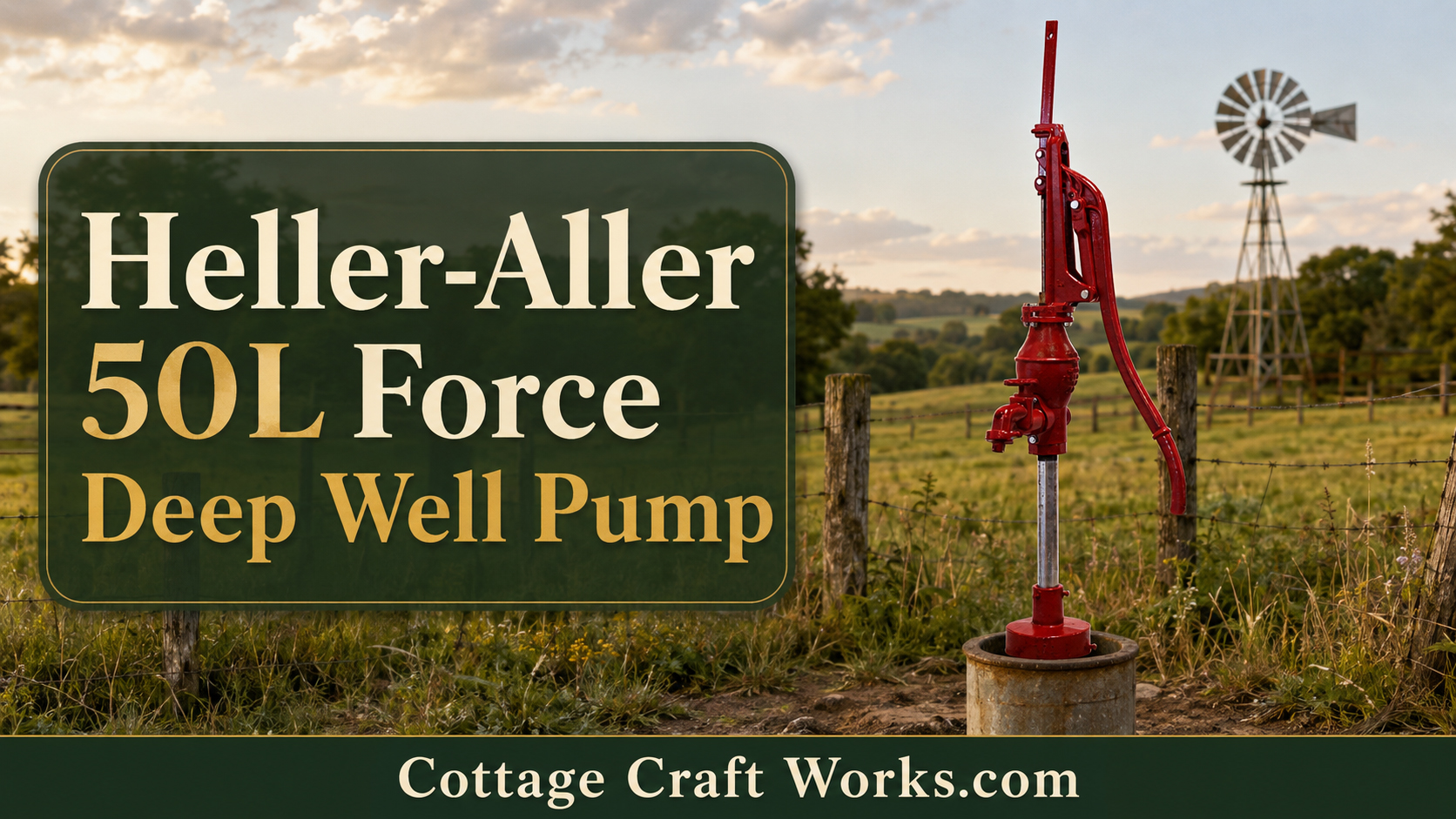
Heller-Aller 50L Troubleshooting, Rebuilding & Repair Guide
Diagnose the complete two-cylinder system before disassembly or pulling the deep-well pump string

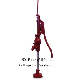
Heller-Aller 50L deep-well force pump. Cottage Craft Works resource banner.
DIAGNOSE BEFORE DISASSEMBLY
The 50L has two working cylinders plus the pump head, discharge plumbing, drop pipe, and sucker rod. A symptom at the handle or spout may originate above ground, in the upper force cylinder, anywhere along the pipe and rod string, or in the submerged lift cylinder.
Plan a careful rebuild and recognize when pulling the deep-well assembly requires a qualified contractor and pump hoist.
The Heller-Aller 50L is repairable, but successful service begins with an accurate diagnosis of the entire two-cylinder system. Work from the discharge plumbing toward the well, checking simple external causes before removing the pump head or pulling pipe. Use authentic parts only after confirming that the pump is stamped Heller-Aller 50-L and record every adjustment, connection and component orientation during disassembly.
Understand the System Before Troubleshooting
The 50L is not a single-cylinder pitcher pump. Its submerged lift cylinder raises water into the drop pipe. The upper double-acting force cylinder receives the water and helps deliver pressure on both strokes. The pump head and linkage drive the sucker rod, while check valves, piston valves and leather seals control the direction of water movement.
Because these parts work as one system, the same symptom can have several causes. Low flow may come from a falling water level, an incorrect stroke, a leaking drop-pipe joint, worn lift-cylinder leathers, a valve that is not seating, or an upper force-cylinder problem. Troubleshooting should isolate the fault rather than beginning with a complete teardown.

USDA Forest Service illustration of a typical reciprocating hand-pump installation showing the pump stand, drop pipe, pump rod and submerged cylinder. Public-domain U.S. Government work; shown as general system orientation, not a Model 50L parts drawing.
Begin With Safety and a Written Baseline
· Stop and lock out any windmill, engine-driven pump jack or other mechanical drive before inspection or adjustment.
· Relieve pressure and isolate the pressure tank or discharge system before opening plumbing or cylinder components.
· Record static water level, pumping water level, recent output, pressure, stroke setting and the exact symptom.
· Photograph linkage positions, rod adjustment, fittings and valve orientation before taking anything apart.
· Keep dirt, scale, lubricants and tools out of the potable-water path; use clean food-contact practices.
· Do not loosen the pump base or any drop-pipe connection until the suspended assembly is positively supported.
DEEP-WELL SERVICE WARNING
Pulling a 50L installation may involve long vertical pipe and rod sections, seized joints, and a heavy suspended assembly. Never rely on people holding the pipe. Use rated hoisting and positive pipe-support equipment, or hire a qualified well or pump contractor.
Troubleshooting Sequence: Simple Checks First
1. Confirm the water source: verify that the lift cylinder remains submerged at the pumping water level and that the well has recovered.
2. Confirm the discharge path: open the correct valves and check for a closed valve, obstructed line, frozen section, failed tank component or excessive system pressure.
3. Observe the pump head: check handle travel, pins, pivots, linkage, fasteners, alignment, and visible leakage while operating slowly by hand.
4. Verify stroke and rod adjustment: confirm that the mechanism is not over-stroking, bottoming, topping out, or side-loading the rod.
5. Listen and feel: note where resistance changes, whether the handle falls, whether strokes feel empty, and whether flow differs on the upstroke and downstroke.
6. Perform a controlled output test: record water delivered over a counted number of full strokes at a repeatable rate.
7. Only then isolate internal sections: upper force cylinder, drop pipe and rod string, and finally the submerged lift cylinder.
Symptom-to-Cause Troubleshooting Table
|
Symptom |
Likely areas to check first |
What the observation may mean |
|
No water after normal startup |
Water level; discharge valves; rod connection; lift-cylinder valves; broken pipe |
An empty-feeling stroke or no recovery may indicate loss of water supply, disconnected rod, severe valve leakage or a pipe failure. |
|
Weak or declining flow |
Pumping water level; stroke; leathers; valve seats; pipe joints |
Worn seals, leaking valves, drawdown or internal leakage can reduce displacement. |
|
Flow on only one stroke |
Upper double-acting force cylinder; piston/valves; stroke adjustment |
One side of the double-acting section may not be filling or discharging correctly. |
|
Will not hold pressure |
Discharge check valve; force-cylinder valves; plumbing; pressure tank |
Water may be leaking backward through a valve or escaping through the system. |
|
Handle falls or will not stay loaded |
Valve leakage; rod failure; severe seal bypass |
Loss of hydraulic resistance can point to a valve not seating, a broken/disconnected rod or major internal leakage. |
|
Hard, binding or uneven stroke |
Rod alignment; bent rod; dry/worn pivots; obstruction; over-stroke |
Stop before forcing it. Continued operation can damage rod, guides, linkage or cylinder components. |
|
Knocking at stroke ends |
Incorrect rod length or stroke; loose linkage; piston contacting limits |
Adjust before continued operation; a mechanical drive can magnify damage rapidly. |
|
Water leaks at pump head or joints |
Packing/seals; gaskets; casting joints; fittings |
Identify whether leakage is external plumbing, a replaceable seal or a cracked/freeze-damaged casting. |
|
Water is dirty after service |
Sanitation; disturbed sediment; casing seal; flushing |
Flush and disinfect as required, then test potable water before use. |
|
Freeze damage suspected |
Drain point; upper cylinder; exposed piping; castings |
Do not pressurize a cracked component. Inspect and replace damaged parts before use. |
Distinguish Pump-Head Problems From Down-Well Problems
Disconnecting or pulling the deep-well assembly should not be the first test. With the drive locked out and pressure relieved, inspect accessible pins, holes, pivots, handle, linkage, rod connection, spout, and discharge fittings. Excessive play, elongated holes, missing retainers, loose fasteners or visible misalignment are above-ground faults.
A pump head that moves freely but produces an empty or inconsistent hydraulic load may point farther down the system. Before pulling, rule out drawdown, closed plumbing, a failed pressure-system component, and an incorrect rod adjustment. If available, use pressure and controlled-output observations to distinguish a delivery problem from a mechanical-motion problem.
How Valves and Leathers Create Common Failures

USDA Forest Service illustration of typical reciprocating pump cylinders, pistons, leathers, and check valves. Public-domain U.S. Government work; use current 50L parts information for the actual rebuild.
Leather cups must seal against the cylinder wall while remaining flexible enough to move without folding or binding. Age, abrasion, mineral deposits, dry storage, sand, and corrosion can cause shrinkage, cracking, glazing, or uneven wear. A worn cup allows water to bypass the piston, reducing output and making the handle feel weak.
Check valves and piston valves must move freely and close squarely on clean seats. Scale, grit, damaged leather, corrosion, or a distorted seat can hold a valve open. Even a small leak can let water drain backward, reduce pressure, or cause one side of the double-acting cylinder to stop contributing properly.
Inspection and Rebuild Decision
|
Condition |
Service response |
|
Leathers hard, cracked, torn or permanently distorted |
Replace with the correct model-specific leather set; do not substitute by appearance alone. |
|
Valve leather or disc damaged |
Replace and verify that the mating seat is clean, smooth and not distorted. |
|
Cylinder wall lightly coated with mineral scale |
Clean by an approved non-damaging method; do not remove material or change the bore. |
|
Cylinder wall deeply scored, pitted or out of round |
Seek manufacturer or qualified rebuilder guidance; new leathers may not seal a damaged bore. |
|
Rod bent, threads damaged or couplings loose |
Replace or repair the affected part and correct the alignment or loading that caused the damage. |
|
Casting cracked or freeze damaged |
Replace the casting; do not weld or pressurize a questionable potable-water pressure component without qualified approval. |
|
Pins and holes badly worn |
Replace worn parts as a set where required and restore correct alignment before powered operation. |
Rebuilding the Accessible Pump Head and Linkage
· Clean the exterior so dirt cannot fall into open water passages.
· Photograph and mark linkage, pin and rod-adjustment positions.
· Lock out all power, relieve pressure, and support any component whose removal could release load.
· Remove pins, retainers and linkage parts without hammering against unsupported castings.
· Inspect the handle, pivot pins, holes, guides, rod connection and fasteners for elongation, bending, cracking or uneven wear.
· Replace parts with confirmed Heller-Aller 50-L components; lightly protect only those external pivots for which an appropriate lubricant is allowed.
· Reassemble in the recorded orientation, secure all retainers and verify free movement through the intended stroke before reconnecting power.
Rebuilding the Upper Double-Acting Force Cylinder
The upper force cylinder is part of the water and pressure path. Work on a clean bench and lay parts out in exact order. Before opening it, relieve all pressure, drain the assembly and positively support the pump and connected pipe. Obtain the current model-specific parts breakdown whenever possible.
· Mark the cylinder orientation and identify which passages serve each side of the piston.
· Open the cylinder without twisting attached piping or forcing cast components.
· Remove the piston, valves, leathers, retainers, and gaskets in sequence; photograph both sides of every valve assembly.
· Inspect the bore, piston, valve seats, stem or rod, threads and castings. Clean mineral deposits without scratching sealing surfaces.
· Install the correct new leathers and valve parts in the same functional orientation. Keep petroleum products and unapproved sealants out of the potable-water path.
· Tighten threaded and bolted joints evenly to the current manufacturer or qualified rebuilder guidance; do not use excess leverage on castings.
· Move the assembly slowly by hand to confirm free travel and correct valve action before pressure testing.
Servicing the Submerged Lift Cylinder
A lift-cylinder rebuild usually requires pulling the drop pipe and sucker rod. That makes it a lifting and well-service operation, not simply a bench repair. Record each pipe and rod section as it is removed, keep the string positively supported, protect threads, and prevent tools or parts from entering the well.
On the bench, inspect the lift-cylinder bore, plunger, cup leathers, standing/check valve, piston valve, rod connection, and inlet. Sand scoring, corrosion, damaged valve seats, or an out-of-round bore can prevent new leathers from restoring performance. Replace parts by confirmed model and cylinder size, not by visual similarity.
Using the Cottage Craft Works Pump Slide During Service
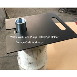
The Cottage Craft Works pump slide fits around the drop pipe immediately below a connector or coupling and rests across a suitable casing top. It can hold the lower pipe string while the next pipe and sucker-rod section is connected or removed. Match the slide to the actual pipe and coupling, confirm that the casing can carry the full load, and keep hoist tension until the load transfer is verified.
The pump slide is a support aid only. It is not a hoist, crane, pipe elevator, lifting clamp, fall-arrest device, or substitute for an experienced crew.
Pipe, Sucker-Rod and Alignment Repairs
· Replace pipe with cracked fittings, damaged threads, deep corrosion, deformation or evidence of leakage.
· Check every rod coupling and threaded connection; a partly separated rod can imitate a failed cylinder.
· Replace bent rod sections and correct casing, guide, or drive alignment before returning the pump to service.
· Use compatible potable-water materials and thread-sealing methods approved for the pipe system.
· Do not mix unknown rod, coupling, or pipe components solely because the threads appear to start.
Stroke Adjustment and Mechanical Drives
Current 50L listings identify adjustable 4-, 6- and 9-inch stroke positions. The selected stroke must suit the pump, cylinder and drive. Incorrect rod length or excessive travel can cause the piston to contact a limit at one end of the stroke. A windmill- or engine-driven pump jack repeats that impact many times and can quickly damage linkage, rod, or cylinder parts.
After service, rotate or move the disconnected mechanism through a complete cycle by hand. Verify alignment, end clearance, and freedom from binding before powered operation. Reinstall guards and keep personnel clear of all moving linkage.
Pressure-System and Discharge Problems
If the pump produces water at an open outlet but performs poorly against the system, investigate the discharge side. Check valves, tank precharge or waterlogging, pressure switch or relief components, closed valves, clogged lines, leaks, elevation head, and friction loss may be responsible. Never defeat a pressure-relief device or exceed the rating of the lowest-rated component.
Freeze Damage and Drain-Back Problems
The current seller information describes freeze protection in which the upper force cylinder is positioned approximately 4 feet down the casing, and the system drains at that point. Actual protection depends on local frost depth, piping slope, valve arrangement, and whether water can drain freely. A blocked drain path or a trapped section can freeze even when the basic installation is intended to be frost-resistant.
After a freeze, inspect castings, pipe, fittings, valves, and seals before pressurizing. Hairline cracks can open under pressure. Replace questionable pressure-bearing parts rather than relying on paint or temporary sealants to hide a leak.
Reassembly, Sanitation and Return-to-Service Test
· Clean and account for every part, tool, and temporary plug before closing the water path.
· Reassemble with confirmed parts, correct valve and leather orientation, secure rod couplings, and properly sealed pipe joints.
· Lower the assembly with controlled hoisting and positive support at every connection.
· Set rod length and stroke so no component tops out, bottoms out, or binds.
· Flush the system until water is clear; disinfect the well and plumbing when required by current state or local guidance.
· Operate slowly by hand while checking for external leaks, abnormal resistance, and equal contribution on both strokes.
· Test output and pressure against the written baseline, then recheck fasteners, pins, retainers, guards, and drain-back function.
· Test potable water through an appropriate laboratory before drinking when the well has been opened, or contamination is possible.
When to Stop and Call a Professional
· The pump stamp or parts identity is uncertain.
· A casting is cracked, a bore is deeply damaged, or a valve seat requires machining.
· The pipe is seized, corroded, or cannot be positively held at the wellhead.
· The installation includes hundreds of feet of suspended pipe and rod or long vertical sections that the crew cannot control.
· A windmill or powered drive requires alignment, guarding, or speed correction.
· The well contains electrical equipment, a pitless adapter, obstructions, or sanitation concerns.
· Local well-service, plumbing, or potable-water rules require licensed work.
Confirm the Pump Before Ordering Parts
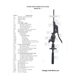
Cottage Craft Works supplies factory replacement parts for Heller-Aller 50-L pumps. Similar pumps from other manufacturers may look nearly identical, but parts may not be interchangeable. Locate the Heller-Aller 50-L identification, photograph the complete pump and damaged part, and record critical dimensions before ordering. Parts categories currently listed include casting, spout, brass valve, force cylinder, hose connection, and lower pump components.
Sources and Illustration Credits
· Cottage Craft Works, “Heller-Aller 50-L Force Pump Parts,” current factory replacement-parts categories and model-identification guidance: https://cottagecraftworks.com/heller-aller-50-l-force-pump-parts
· Cottage Craft Works, “Heller Aller Windmill Double Acting Force Pump Model 50L,” current configuration and operating information: https://cottagecraftworks.com/heller-aller-windmill-double-acting-force-pump-model-50l
· Hitzer Inc., “Model 50L Windmill Force Pump,” current manufacturer product information: https://hitzer.com/our-products/water-pumps/model-50l-windmill-force-pump
· USDA Forest Service, Engineering Field Notes, “Hand Pump Operation and Maintenance,” Vol. 13, Jan.-Feb. 1981. Public-domain U.S. Government work: https://www.fs.usda.gov/eng/pubs/pdfpubs/pdf81713801/pdf81713801.pdf
· USDA Forest Service, Operation and Maintenance Manual for Hand Pumps, 1999. Public-domain U.S. Government work: https://www.fs.usda.gov/t-d/pubs/pdf/99231209.pdf
Disclaimer
This resource is for general educational and planning purposes only. It is not the current Heller-Aller factory service manual, a site-specific diagnosis, an engineering design, a lifting plan, a safety program, a water-quality directive, or a substitute for qualified inspection. Pump age, previous repairs, well construction, water chemistry, pressure, loads, equipment, codes, licensing and sanitation requirements vary. Verify pump identity, current replacement parts, procedures, and component compatibility before repair. Lock out mechanical drives, relieve pressure, and positively support suspended equipment. Deep-well service involves long pipe and rod sections, heavy tools, pinch points and the risk of injury or dropping equipment into the well. The Cottage Craft Works pump slide is a pipe-support aid only; it is not a hoist, crane, lifting clamp, fall-arrest device or guarantee against slippage. Consult the manufacturer, a qualified rebuilder or a licensed well or pump contractor whenever the correct procedure or condition of a component is uncertain. Cottage Craft Works and CCW LLC assume no responsibility for injury, contamination, property damage, equipment loss, well damage, or other consequences arising from use or misuse of this information or any product.