
Article
Heller-Aller Fig. T Brass Cylinder Pump Installation Guide
How do you install and prime a Heller-Aller Fig. T Brass Cylinder Pump?
Install the Heller-Aller Fig. T on a solid mounting surface above a cistern or shallow well where the vertical suction lift is approximately 20 feet or less. Connect the pump's 1-1/4-inch inlet to an airtight suction pipe, orient the spout and handle for proper clearance, and securely bolt the pump to the mounting surface. To prime the pump, pour water into the top while operating the handle until the pump draws water and produces a steady flow from the spout.
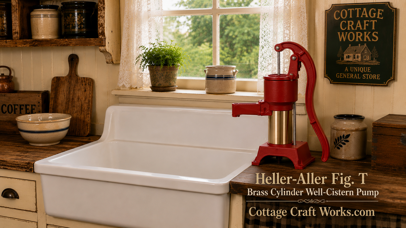
The Heller-Aller Fig. T is a single-acting brass-cylinder hand pump designed for cisterns and shallow wells with a suction lift of approximately 20 feet or less. Proper installation requires a secure mounting surface, an airtight 1-1/4-inch suction pipe, correct pump placement, and proper priming before operation.
This guide walks through installation from planning the location through the first successful pumping of water.
Installing a Heller-Aller Fig. T Brass Cylinder Pump
The Heller-Aller Fig. T is a relatively simple hand-operated pump, but the quality of the installation has a major effect on how well it performs.
Many problems blamed on the pump—difficulty priming, loss of prime, poor water delivery, or failure to lift water—can actually originate in the suction piping or installation.
Before mounting the pump, plan the entire installation from the pump down to the water source.
Understand the Fig. T Before Installation
The Fig. T is intended primarily for cistern and shallow-well applications.
Important specifications include:
Maximum Suction Lift: Approximately 20 feet
Cylinder: 3-inch I.D. brass cylinder
Stroke: 3 inches
Suction/Drop Pipe Connection: 1-1/4 inch
Operation: Single-acting
The approximately 20-foot rating refers to vertical suction lift, not simply the total length of pipe used in the installation. Most cisterns and hand-dug wells were positioned outside of the kitchen area or in a basement directly under the kitchen, making it easy to drop a pipe straight down or slanted down to reach into the water.
Step 1 — Determine the Vertical Suction Lift
Before installing the pump, determine the vertical distance between the pump and the water level.
This measurement is particularly important with a shallow-well pump because atmospheric pressure limits how far a suction pump can practically lift water.
The Fig. T is intended for installations where the suction lift is approximately 20 feet or less.
Remember that the water level can change.
A well that reaches water at 15 feet during the wet season may have a considerably lower water level during dry weather. The installation should therefore be planned around the expected operating water level rather than simply the water level observed on one particular day.
Step 2 — Select the Pump Location
The Fig. T can be mounted where its spout can conveniently discharge water into a:
- Sink
- Basin
- Bucket
- Container
- Cistern-use area
- Other suitable receiving point
Choose a mounting location that provides enough clearance for the handle to travel through its complete operating stroke.
Also make sure there is sufficient access for future maintenance and removal of the pump.
Step 3 — Prepare a Solid Mounting Surface
The pump must be mounted to a solid, stable surface.
Repeated movement of the handle places alternating loads on the mounting points. A weak or flexible mounting surface can eventually loosen the pump and piping.
The original installation information calls for mounting holes drilled for 5/16-inch hardware.
The mounting reference also provides for a central opening of approximately 1-7/8 inches for the pipe connection.
Important Mounting Template Precaution
A historical or reproduced Heller-Aller mounting diagram can be useful for understanding the hole arrangement, but do not use a printed or downloaded reproduction as a drilling template without first verifying its dimensions against the actual pump.
Printing, scanning, PDF conversion, and printer scaling can change the size of a drawing.
Whenever possible, place the actual pump in its intended position and mark the mounting holes directly from the pump.
Step 4 — Position the Pump Before Drilling
Place the Fig. T in its intended location.
Check:
Spout direction — Make sure water will discharge where intended.
Handle side — Make sure the handle has sufficient operating clearance.
Pipe location — Verify that the suction pipe can run directly beneath the pump without unnecessary bends or interference.
Service access — Leave enough room to work on the pump later.
Once everything is correctly positioned, mark the mounting holes and center pipe opening.
Step 5 — Drill the Mounting Holes
The original installation specifications call for:
Four mounting holes: 5/16 inch
Central pipe opening: Approximately 1-7/8 inches
Mounting bolts: Four 5/16-inch × 1-1/2-inch bolts
The exact mounting arrangement should always be checked against the pump actually being installed.
This is especially important with older pumps that may have been repaired, modified, or assembled using components from different production periods.
Step 6 — Install the 1-1/4-Inch Suction Pipe
The Fig. T inlet is tapped for a 1-1/4-inch suction or drop pipe.
Original instructions reference 1-1/4-inch galvanized pipe, while suitable modern installations may also use properly selected PVC components.
Regardless of the pipe material, the suction side must remain airtight.
This is one of the most important principles in installing a shallow-well hand pump.
Why an Airtight Suction Line Matters
The pump does not simply "pull" water upward through the pipe.
Operation of the plunger reduces pressure within the cylinder and the suction line. Atmospheric pressure acting on the water source then helps move water upward into the pump.
An air leak can prevent the pump from developing enough vacuum to raise the water.
A connection can therefore be:
Watertight against leaking water outward but still leak enough air inward to prevent proper pumping.
For that reason, carefully seal and tighten every suction-side connection.
Step 7 — Keep the Suction Installation Simple
Whenever practical, minimize:
- Unnecessary elbows
- Excessive fittings
- Restrictions
- Poorly fitted connections
- Potential air-leak points
Every additional connection creates another potential location for an air leak.
A properly installed suction line should provide a dependable, unrestricted path between the water source and the pump.
Step 8 — Connect the Pipe to the Fig. T
Bring the 1-1/4-inch suction pipe through the mounting opening and connect it to the threaded inlet at the bottom of the Fig. T.
Support the piping appropriately.
Do not rely on the pump casting or mounting bolts to support an excessive amount of unsupported pipe weight.
Make sure the pump remains correctly oriented toward the sink or discharge area while tightening the connection.
Step 9 — Secure the Pump
With the suction connection completed, secure the Fig. T to the mounting surface.
The original instructions specify four 5/16-inch × 1-1/2-inch mounting bolts.
Tighten the mounting hardware evenly so that the pump sits firmly on the surface.
Do not use uneven bolt tightening to force a pump onto a warped or irregular mounting surface.
Step 10 — Prime the Fig. T
A newly installed or completely drained Fig. T normally needs to be primed before it can begin lifting water.
The original installation procedure calls for pouring water into the top of the pump while operating the handle.
Add water and continue operating the handle until the pump begins drawing water and a free, steady flow is established from the spout.
Priming wets the internal leather and fills the pump sufficiently for the plunger and valves to begin creating the necessary pumping action.
Step 11 — Check Initial Operation
Once water begins flowing, continue operating the pump for several strokes.
Watch for:
Steady water delivery
The flow should become consistent once the suction line and cylinder are filled.
Unusual resistance
The handle should operate smoothly without binding.
Water leakage
Inspect connections and the pump body.
Loss of prime
If the pump repeatedly loses prime, inspect the suction system and internal sealing components.
Note: It is normal to experience discolored grayish water from the pump until the pump leathers have conditioned. Pump it several times to flush out the pump and joint compound.
If the Fig. T Will Not Prime
Do not immediately assume the pump itself is defective.
Check the installation first.
Common areas to investigate include:
Air leaks in the suction line
Even a small air leak can interfere with pumping.
Loose pipe connections
Check all threaded suction-side connections.
Water level too far below the pump
Verify that the actual vertical suction lift is within the Fig. T's operating range.
Dry or worn leather
An old or dried plunger leather may not seal sufficiently against the brass cylinder.
Check-valve sealing
A check valve that does not seal can allow water to fall back between strokes.
These subjects can then be addressed in detail in our separate Fig. T Troubleshooting and Rebuilding Guides rather than overloading the Installation Guide.
Freeze Protection
The Fig. T has an important feature for installations exposed to freezing temperatures.
To help drain the pump, raise the handle completely. This allows the cylinder and supply line to drain rather than leaving water trapped where it can freeze.
Do not assume that raising the handle automatically protects every installation from freezing. The piping must also be installed so that water can actually drain rather than becoming trapped in low points or improperly pitched sections.
After Installation
Once the Fig. T is operating correctly:
- Inspect all mounting hardware.
- Check the suction connection.
- Operate the pump through several complete strokes.
- Confirm a steady discharge.
- Verify that the handle has full clearance.
- Check the mounting surface for movement.
- Make sure the pump can be drained if exposed to freezing conditions.
A properly installed Fig. T should operate smoothly, with neither the pump body nor the mounting surface moving during normal use.
Sanitizing a New Pump Before First Use
When installing a new pump on a cistern or well used for drinking water, the pump and connected water system should be disinfected before use. Use fresh, unscented household chlorine bleach according to the appropriate well or cistern disinfection procedure, and operate the pump until chlorinated water has passed through the pump and spout. Allow the required contact time, then thoroughly flush the system with clean water until chlorine is no longer present before drinking.
Cottage Craft Works Note: The amount of bleach required depends on the type and volume of the water system. Do not use a fixed bleach amount for every installation. For cisterns, wells, or questionable water sources, follow CDC or state/local health-department disinfection guidelines.
I think this is short enough to fit naturally immediately after the priming instructions on both manuals.
Photos
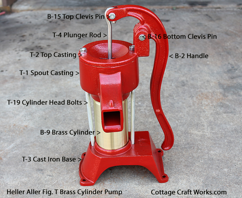
Heller Aller Fig T Parts Locations
Downloads
- Download
Original Heller Aller Fig T Manual